
History and Background
Specifics on subject building
- Large “big box” home improvement retail store
- 100,000 sq. ft. of fire sprinkler system coverage area
- 5 wet pipe risers serving the building – average system volume 1,500 gallons
- In‐rack fire sprinkler system
Corrosion related leak history
- Frequent leak history across all zones
- High risk due to business continuity disruption and
product damage
Water supply – municipal drinking water
Fire sprinkler system design configuration
- Large gridded systems with 6’ of rise from the back of the building to the front
- Feed main was located at the back of the building and floating main was located at the front of the building
- Single in‐rack system protecting paint department
Fire sprinkler piping materials
- Rolled groove schedule 10 black steel piping for the mains and schedule 40 black steel piping for the branch lines
- Repair and replacements of piping over multi‐year period
Preliminary Assessment Work
In order to determine the root cause for the corrosion related leaks within the fire sprinkler system a corrosion profile study was performed. The profile included:
- Leak frequency and locations
- Pipe replacement history
- Service history of the fire sprinkler systems
- Analysis of the topography of the fire sprinkler systems
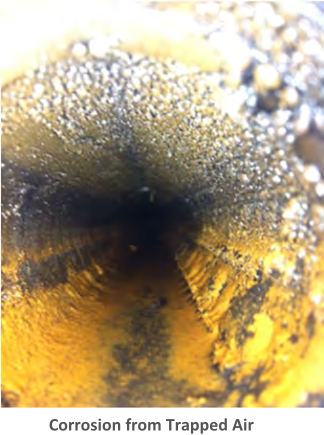
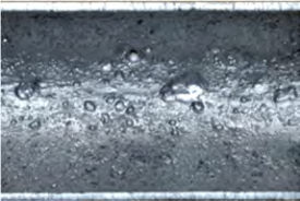
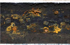
The profile determined that the root cause for corrosion within the systems was oxygen attack of the black steel piping. The majority of the damaged piping was found at the air/water interface adjacent to trapped pockets of air within the piping at the front of the building. Because of the system design, there were areas within the fire sprinkler piping network which trapped large amounts of air after filling the systems with water.
Because the fire sprinkler contractor has been trained and certified in the ECS Nitrogen inerting protocol they are capable of performing any future service on the systems. If remodels require the modification of a sprinkler zone the contractor can maintain the nitrogen inerted atmosphere within the drained system while performing modifications to the system.